
Abstract
This chapter will provide students with the following knowledge.
You have full access to this open access chapter, Download chapter PDF
1 Learning Objectives
This chapter will provide students with the following knowledge:
-
1.
An understand of the design process and where CAD is applied within the process.
-
2.
A general understanding of the different CAD systems, their application and file structures.
-
3.
An insight into the use of CADD as a design tool.
-
4.
An awareness for the various digital prototyping and visualisation tool.
2 Introduction
This section provides a brief introduction to the design process, how CAD/CAM fits into this process and a brief overview of the various CAD/CAM technologies. For a more detailed understanding of the topics covered in this section, references are included.
3 The Design Process and CAD
The design process is a method, used by designers and engineers, to divide a project into manageable steps to find a solution to a problem. Typically, the design process consists of five steps: 1. Briefing and task clarification, 2. Concepts generation, 3. Refinement and prototyping, 4. Final design and documentation and 5. Manufacturing (Bonollo, 2016, p. 17–18), refer Diagram 1.

Double-diamond diagram of the design process (Design Council, 2021)
Importantly, the design process is not a linear process because at any step during the design process a previous step can be revisited to gather more information or to re-consider the design, etc. Below is a brief overview of the design process steps and the application of CAD.
Briefing and Task Clarification involves understanding the client brief, defining the problem and the user, gathering information (researching the market, ergonomics, anthropometrics, standards, etc.), quantities, cost estimates, materials, processes, preparing design guidelines for the next steps of the design process, brainstorming possible ideas and preparing a project timeline. Identifying suitable materials and manufacturing processes is an important consideration as these will greatly influence the design to ensure it can be manufactured within the expected retail costs. The technologies needed to undertake the project, such as suitable CAD packages, 3D printing, etc., will also need to be identified to ensure the viability of the project.
Concept Generation is where a variety of alternative ideas are generated as possible solutions to the design problem. As many concept ideas as possible are generated, typically five or more that are originated from all different directions and fields via an out-of-the-box, free-flowing cognitive process known as divergent thinking. Typically, these concepts are hand generated using pencils and paper or via multi-touch displays such as Wacom tablets. However, with both techniques a certain level of free-hand sketching skills is required to adequately communicate the design intent. At this stage rudimentary prototypes are also sometimes produced to evaluate ideas. Today CAD is being used more often at this early stage of the design process to generate quick models for early testing and verification. This is due to advancements in CAD that have enable 2D CAD to be transferred to 3D CAD and other features such polygon modelling to generate quick complex surfaces that can then be converted to solid geometry. An example of polygon modelling is the Freestyle tool in CREO CAD software where a simple starting geometry such as a sphere, cube or flat surface can be easily pulled and pushed into the desired shape and then converted into a solid.
Refinement and Prototyping involve narrowing down the ideas to one final design through a cognitive process referred to as convergent thinking. Again, this commonly involves same freehand skills and or the use of Wacom tablets as in the previous step. Generally, a hand-generated workshop prototype is also made to verify design elements such as ergonomics, proportions, size, functionality and aesthetics. As per the concept generation step, CAD is being used more often at this step to model, test and 3D print the design to verify its design integrity.
Final Design and Documentation. This is where the CAD model is developed to be ready for manufacture. Here the CAD model can be numerically analysed via a range of CAD analysis tools such as Finite Element Analysis (FEA) both static and dynamic, etc., to ensure the structural integrity of the design, to confirm that all the parts fit together as intended, and 3D printed for further verification.
This step also involve the preparation of technical drawing and documentation for manufacturing requirements.
Once the design meets all the requirements of the brief, it can then proceed to the next step.
Manufacturing. This entails several phases as follows.
-
Phase 1. Source suitable manufactures and find out what file format(s) they require for the part files.
-
Phase 2. Send the part files, technical drawings and manufacturing requirements to the manufacturer(s) to check the parts suitability for manufacture, provide quotes to manufacture each part and recommend any changes to improve manufacturing.
-
Phase 3. Any recommended changes from the manufacturer(s) will require further edits to the CAD model, technical drawings and the manufacturing requirements.
-
Phase 4. Once the design is considered ready for manufacture a working prototype is produced to test and verify the integrity of the design in its working environment.
-
Phase 5. If changes are required, the CAD model is updated, and the manufacturing phases are repeated as required.
-
Phase 6. Design is manufactured.
4 The Design Process Versus Design Thinking
Whereas the design process is a way of dividing a problem into manageable chunks, design thinking (as discussed in Chap. 3) can be applied at any point along the design process to find solutions to ill-defined problems that emerge (Dam & Siang, 2018). Said another way, the design process is a series of steps while design thinking is a mindset that enables innovative solutions to emerge (Prud'homme van Reine, 2017, p.64, 70).
5 Cad Systems
Today there are numerous advanced computer-aided design (CAD) software packages for modelling 3D objects. However, all these packages are based on two systems, the first is parametric 3D modelling, the second is direct 3D modelling.
Parametric 3D Modelling : With this system, each entity in a model is constructed of features that are listed in a feature history tree. A feature can be a cut, extrude, revolve, datum plane, datum axis, datum point, sketch, hole, etc. Each feature, entity and all their relationships, parameters (length, width, height, radius, diameter, force, etc.), and their position within the assembly are easily tracked via the feature history tree. The parametric 3D modelling innovation emerged in 1987 when Parametric Technology Corporation (PTC) released Pro/Engineer (ProE) CAD software. Since its first release, PTC has made numerous enhancements to ProE and in 2011 renamed it to CREO. Today the parametric concept is used in most CAD programs as seen in Table 12.1 (Tornincasa & Di Monaco, 2010, p II-9 & II-17; Ault & Phillips, 2016).
In Table 12.1, level refers to the capability of the package. A high-level package offers more features and better features to generate complex geometries more easily and quickly than mid-level packages. However, high-level packages take longer to learn.
A benefit of the parametric concept is that the model is fully associative so that if a parameter in a part, assembly or drawing is changed then the related parts, assemblies and drawings will automatically update to reflect the change. For example, take a shaft that fits into a hole with a set clearance between them. If the diameter of the shaft (parameter 1) is changed, then the diameter of the hole will automatically update to maintain the set clearance (parameter 2). This ensures that the integrity of the model and the design intent is maintained.
However, on the negative side parametric 3D modelling systems requires specialised operators with expert skills and knowledge that takes considerable time and training to acquire (Tornincasa & Di Monaco, 2010, p II-5 to II-7), (Alba, 2018, March). Furthermore, considerable planning is required to ensure that the model, features and files are properly structured to avoid problems as the model evolves. As seen in Image 1, CREO has a feature history tree displayed on the left-hand side of the window that can be used to manage and edit the model.

3D model of a powered joint. Creo (version 7, 2020) parametric 3D modelling system from parametric technology corporation (PTC)
Direct Modelling : With this system, there are no parametric associations. Therefore, model features can be quickly and easily edited by moving, rotating, deleting, etc. features such as faces and edges without having to consider the model history (Tornincasa & Di Monaco, 2010, p II-7). This also makes it easier for a designer to work on a model that was started by someone else. Direct modelling systems can be very effective in the early stages of the design process as models can be quickly and easily generated. Another advantage is that direct modelling systems only take a short time to learn.
The disadvantage of direct modelling is that editing operations can lead to parts that are no longer dependable. For example, if the centreline of a rotating shaft has been accidently moved it can cause the shaft to interfere with other parts. Or if a change has inadvertently altered the tolerances between two parts it could lead to excessive wear when in operation.
Many of the CAD systems today offer a hybrid approach that merges both parametric 3D modelling and direct modelling (Tornincasa & Di Monaco, 2010, p II-8). These systems preserve the integrity of the model while gaining the flexibility and freedom of direct modelling.
6 CAD File Types
There are generally three main types of files that are used when building 3D parametric CAD models that are going to be manufactured: assembly files, part files and drawing files. The purpose of assembly files is to hold all the part files together, whereas part files represent the individual components that in real life cannot be broken down any further. Finally, drawing files are used for generating 2D technical drawings (also known as engineering drawings) of the model and its parts.
7 CAD Parametric Modelling—Assembly and Part Files
As previously noted, CAD is commonly employed at the ‘final design and documentation stage’ of the design process where the design has been narrowed down to one final concept. The reason CAD is typically introduced at this stage is because all the details have been decided and most importantly no major fundamental changes are foreseen. Here the details refer to the: shape, size, number of parts and their layout, materials, weight, manufacturing process, functionality, ergonomics, environmental and social considerations, aesthetics, etc. The fundamental changers refer to sweeping changes to the details that would affect the structure of the part files and their parametric associations.
Using parametric modelling, the design can be constructed in an assembly with multiple parts built to very high accuracies. This enables the CAD model to be digitally tested for correct fit between parts, structural integrity using finite element analysis (FEA), proper articulation of parts, manufacturability, aesthetics by generating realistically renders, physical verification through 3D printing, etc. Importantly, at any point during the CAD modelling process the model can be tweaked as needed.
Accordingly, CAD has greatly reduced the time needed to design products and release them onto the market.
Assembly and Part File Structure and Referencing: Before starting a 3D CAD parametric model, the structure of the files in the assembly requires considerable planning. This is important to ensure the model can be easily edited at any time by carefully considering how features are referenced to avoid circular references that can be formed between files in an assembly. The problem with circular reference is that they can cause the assembly to stop regenerating or even become unstable. Circular references are typically formed when editing a part that was created earlier in the assembly (the parent ‘A’) and referencing it to its child (part ‘B’ that was built later in the assembly). The reference sequence for this circular reference looks like A < B < A. Most CAD systems will alert you if any circular references have been created; however, this generally only happens when the whole assembly is regenerated. Therefore, it is important to regularly regenerate the whole assembly to check for circular references before they become too imbedded in the reference scheme. The best practice to avoid circular references is to only take references from files created before the one you are working in. In the feature history tree, these are files above the one you are worked in. In a 3D parametric model, an example of a feature history tree (or model tree ) can be seen in Image 1, on the left side of the window. The feature history tree also represents the file structure where in Image 1 it starts with the assembly file (DRIVE_JOINT.ASM that was created first) followed by all the part files.
In the feature history tree, each part file can also be expanded to list all the features that are used to model the part geometry. This can be seen in Image 2 where the feature history tree (Model Tree) for the ‘DRIVE_JOINT_SKEL.PRT’ file has been expanded to show all its features.

In the model tree, seen on the left side of the window, the DRIVE_JOINT_SKEL.PRT part file has been expanded to show all its features. Model created in Creo (version 7, 2020) parametric 3D modelling system from Parametric Technology Corporation (PTC)
With 3D CAD parametric modelling, panning is also required when constructing each part (Bodein et al., 2014, pp 136). Within each part file, the choice of features, how they are organised and the choice of references are important to maintain performance of the software and hardware and ensure that the part can be easily modified if needed. A poorly constructed CAD model can take considerably more time to build, edit and regenerate than a well-constructed model. Therefore, before starting a CAD model there are some essential modelling guidelines, for structuring and building assembly and part files, that operators need to know.
General CAD Modelling Guidelines for Assembly Files: When designing a product, designers typically start by sketching and drawing the product in its assembled form. This allows the designer to develop the design with all its parts as the design evolves. Developing the design from the top down also applied to modelling and designing a product on CAD. It must be noted that although CREO is used in this chapter to illustrate how CAD works, the modelling guidelines can be applied to all parametric 3D CAD modelling packages.
Below are modelling guidelines for parametric CAD assembly files :
-
1.
File Naming —Before starting a CAD model, the first thing is to decide on a naming convention for all the files. This is important so that files can be managed, and file names are not repeated, and can be easily found.
-
2.
Assembly file—With products that have more than one part, the CAD modelling process typically starts with an assembly. In CAD, an assembly file should generally only contain some datum features and the part files. The datum features are typically a datum coordinate system and or x, y, z datum planes that are used as references to place all the part files into the assembly, as seen in Image 3.
Image 3 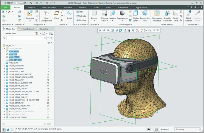
In the model tree, seen on the left side of the window, the assembly datum features are highlighted in blue and are seen in green in the model window. Model created in Creo (version 7, 2020) parametric 3D modelling system from Parametric Technology Corporation (PTC)
-
3.
Referencing —It is important to employ a simple assembly referencing regime. This can be achieved by using the first part file in the assembly as a reference file that contains all the references to ‘Drive and define the Model’. In CREO, this reference file is called a Skeleton file; it can be automatically created and is placed after the assembly file as seen in Image 2. The reference file should only contain basic parametric elements that will be used as references by all the other part files in the assembly. Basic parametric elements are sketched lines, sketched curves, point, centrelines, axis, surfaces (as opposed to faces from solid geometry) and planes that have been explicitly created by the user to be utilised as reference entities to ‘Drive and define the Model’. What is meant by ‘Drive and define the Model’ is that by editing any Basic Parametric Element in the reference file the rest of the part files in the assembly and their feature will automatically update.
-
4.
The only features that should not be included in a driving file are solid features.
-
5.
Solid features should only exist in the part files following the reference-file in the assembly.
-
6.
Do not take references from solid features.
-
7.
Reassemble (reuse) the same part. A typical case is when there are several of the same fastener in an assembly. It is much faster, less complex (less features in the assembly) and easier to simply reassemble the same part in another location in the assembly than continually rebuilding the part.

General Modelling Guidelines for Part Files: When a product consists of only one part then the following guidelines can be applied:
-
1.
Break down the part to determine what are the basic functional geometric elements (squares, rectangles, cubes, cuboids, spheres, etc.). Decide the features (CAD tools) that will be used to model each element, how they interface with each other and their reference links.
-
2.
Construct the references - The first features in a part file should comprise basic parametric elements that will be used as references by all the other features in the part file. Basic parametric elements are sketched lines, sketched curves, points, centrelines, axis, surfaces (as opposed to faces from solid geometry) and planes that have been explicitly created by the user to be utilised as reference entities to ‘Drive and define the part’. Keep sketches of basic parametric elements as simple as possible.
-
3.
Create the solid geometry by taking references from basic parametric elements. Try not to take references from any solid geometry.
-
4.
If needed, it is always best to edit the basic parametric elements or insert some more basic parametric elements rather than taking references from solid geometry.
-
5.
Create rounds, shells and draft angles last when modelling your parts.
-
6.
Do not take references from rounds, shells and draft angles.
Example Assembly and Part File Structure: An example of a CAD parametric assembly file structure with parent–child reference links is shown in Diagram 2. The file structure starts with an ‘Assembly File’ followed by ‘Reference Part File-A’ which is the only file referenced to the ‘Assembly File’. This means that all the basic parametric elements can reside in ‘Reference Part File-A’ to ‘Drive and define the model’ (the whole assembly). Therefore, all the other parts and sub-assemblies in the assembly can be referenced to ‘Reference Part File-A’.

Example assembly file structure with parent–child reference links
In Diagram 2, all the part files in ‘Group 1’ were created in the assembly with all their references, to construct the solid geometry, taken from the basic parametric elements in ‘Reference Part File-A’.
All the part files in ‘Group 2’ were created in the ‘Sub-Assembly File’ with all their references, to construct the solid geometry, taken from the basic parametric elements in ‘Reference Part File-B’. The sub-assembly was created outside the ‘Assembly File’ and imported into the ‘Assembly File’. The ‘Sub-Assembly File’ was then referenced to ‘Reference Part File-A’. This means that the position of the sub-assembly is defined by ‘Reference Part File-A’.
Finally, all the parts in ‘Group 3’ were created separately outside the ‘Assembly File’ and then imported into the ‘Assembly File’. Each ‘Group 3’ file contains its own basic parametric elements to reference the solid geometry within the file. In the ‘Assembly File’ the position of each ‘Group 3’ file is defined by referencing them to ‘Reference Part File-A’.
The benefit of this file structure and referencing method is that all the files in the ‘Assembly File’ (the assembly model) can be managed via ‘Reference Part File-A’. This method greatly reduces the problem of having to make changes to every part file in the assembly to modify the model.
CAD Model Validation: Today most CAD systems have easy-to-use design validation tools. With these tools’ materials can be assigned to each part complete with material properties such as density, tensile strength, compressive strength, Young’s modulus, Poisson’s ratio, specific heat capacity, thermal conductivity, hardness, etc. With these properties, the weight of parts and the whole model, including its structural integrity, thermal integrity, etc. can be analysed and validated. An example of a finite element analysis (FEA) is shown in Image 4.

Finite element analysis (FEA) of a Snowboard Binding Highback made from carbon fibre and Kevlar. The analysis shows the deflection and stresses resulting from a force applied to the part that simulates what would happen in the real world. Analysis was generated in Creo (version 7, 2020) parametric 3D modelling system from Parametric Technology Corporation (PTC)
Validation tools can also apply colours and surfaces finish, such as textures, to the model surfaces. The model can then be photo realistically rendered to validate its aesthetic quality as seen in Image 5.

Rendering of a Hexapod Robot. Modelled in Fusion 360 parametric 3D modelling system from Autodesk. (Derivative of 'Anansi Hexapod Robot' by Bryce Cronin/CC BY 4.0. www.cronin.cloud/hexapod)
The model can also be sectioned to check how the parts fit together (see Image 6) and exploded to see all the parts (see Image 7).

A section view of a Hexapod Robot. Modelled in fusion 360 parametric 3D modelling system from Autodesk. (Derivative of 'Anansi Hexapod Robot' by Bryce Cronin/CC BY 4.0. www.cronin.cloud/hexapod)

An exploded view of a Hexapod Robot. Modelled in fusion 360 parametric 3D modelling system from Autodesk. (Derivative of 'Anansi Hexapod Robot' by Bryce Cronin/CC BY 4.0. www.cronin.cloud/hexapod)
8 CAD Parametric Modelling—Drawing Files
CAD drawing files are used to generate technical drawings for communicating manufacturing and assembly instructions. Today there is less need for technical drawings to manufacture parts. This is because CAD part files can be converted into various formats and sent directly to manufacture (Xometry, 2020). However, it’s important to always contact the manufacturer to see what file format they require or what technical drawings are needed.
Generating technical drawings of CAD models is a fairly easy process but some basic knowledge is required as follows:
Technical Drawing Standards: Technical drawings need to follow strict standards to ensure instructions are unambiguous. These standards vary from country to country, so it is important to become knowledgeable with the standards in your country before preparing technical drawings to send out to manufacture. The technical drawing standards are comprehensive in describing the way that objects, assemblies, parts, features (holes, shafts, chamfers, countersinks, threads, fasteners, fillets, centrelines, assemblies, etc.), dimensions, text, line thicknesses etc. are presented on drawings. If the standards are incorrectly applied, it can lead to faulty parts being manufactured. Although most countries have their own technical drawing standards, most are based on the International Organisation for Standards (ISO) standard ISO 128–1:2020 (ISO, 2021). In Table 12.2 are technical drawings standards for some countries.
Technical Drawing Sheet Structure: When generating technical drawings for products that consist of more than one part (in an assembly), it is important to have some structure to the set of drawing sheets. One way is to organise the sheets into three groups as follows: Group one contains the assembly sheet(s) that shows the product in its assembled form. This is the first drawing sheet(s) in the set. Generally, only the overall dimensions of the product are shown on the assembly drawings. This allows the manufacturer to understand what the product looks like, get a sense of its size, how all the parts fit together and how to assemble the product, as seen in Image 8.

Example technical assembly drawing of a hinge. Created in Creo (version 7, 2020) parametric 3D modelling system from Parametric Technology Corporation (PTC)
Group Two contains the parts list sheet(s). Here a description, material, quantity required and other information for each part is listed in a table, as seen in Image 9.

Example technical assembly parts list drawing of the hinge. Created in Creo (version 7, 2020) parametric 3D modelling system from Parametric Technology Corporation (PTC)
Group Three contains the drawing sheet(s) for each part. The technical drawing sheet(s) for each part need to contain all the information required to manufacture the part without having to refer to the assembly and parts list, as seen in Image 10. This enables drawing sheets for parts that require different manufacturing processes (fabrication, casting, forging, machining, etc.) to be separated and sent to different manufacturers who have the requisite manufacturing capabilities. For example, if a product contains two parts in an assembly where part one is sand cast and part two is fabricated from sheet metal. Then in the drawing set, Sheet 1 can be the assembly drawing, sheet 2 the parts list, sheets 3 to 5 for part one and sheets 6 and 7 for part two. Consequently, to make the two parts: sheets 3 to 5 can be sent to a manufacturer who specialised in sand casting while sheets 6 and 7 can be sent to a sheet metal fabricator.

Example technical part drawing of the Hinge_Bent_Arm part. Created in Creo (version 7, 2020) parametric 3D modelling system from Parametric Technology Corporation (PTC)
Technical Drawing Sheet Sizes: The sheet sizes for technical drawings are ISO-A and ISO-B. It is important to refer to the standards in your country to see which one is preferred. It is recommended that all technical drawing sheets have a border that denotes the extent of the information contained on the sheet. The typical recommended sheet sizes and borders are as shown in Tables 12.3 and 12.4.
Each drawing sheet must also have a title block that can be customised to a certain degree to suit the requirements of the author or organisation. Examples of title blocks can be seen in Images 8, 9 and 10. It is important to refer to the standards in your country to see the requirements and options for title blocks.
Technical Drawing Orthographic Projections: In technical drawings 3D objects are typically represented by 2D views known as orthographic projections. The purpose of orthographic projections is to clearly communicate the shape and dimensions of objects. This is achieved by representing the object in various orthographic views, such as front view, side views, top view, bottom view, section views, etc. and applying dimensions to the views as seen in Images 8 and 10. Orthographic views are typically represented as unshaded line drawings, however 3D rendered perspective views can also be included to help communicate the shape of the object as seen in Images 8 and 10.
There are two types of orthographic projection—first angle and third angle projection as seen in Image 11.

First and third angle projections. (Williams, 1993)
On a technical drawing sheet, the type of orthographic projection applied must be stated with a symbol as shown in Image 12. Furthermore, in a set of drawings all the views must be presented in either first or third angle projection. There must not be a mix of first and third angle projections in a set of drawings. The application of third angle projection in technical drawings can be seen in Images 8 and 10. Although third angle projection is the most common method used, it is important to refer to the standards in your country to see which one is preferred.

Technical Drawing Scales: It is recommended that technical drawing orthographic views should ideally be drawn to the following scales. The recommended ISO scales for mechanical technical drawing are shown in Table 12.5.
Reading a Technical Drawing: For products that consist of more than one part (in an assembly), the first step is to understand what the assembled product looks like, its size, how many parts there are, what material each part is made of and how all the parts fit together. This is revealed by reading the assembly sheet(s) in conjunction with the parts list. The parts list also list which sheet(s) in the set contains the details for each part.
The second step is to read the drawing sheet(s) for each part to understand the shape, dimensions and all the necessary information to manufacture the part. As seen in Image 10, there are two orthographic views of the HINGE_ARM_BENT part that describe its shape and dimensions. For more complex shapes, there may be more views including section views and detail views to fully describe the part. Furthermore, this information may be spread over more than one sheet. Also seen on Image 10 is a shaded perspective view of the part that is useful for visualising what the parts looks like. The other information on the sheet is the material that is specified as ‘STAINLESS STEEL 304 SHEET’, and therefore, an appropriate manufacturing process would be sheet metal cutting and bending. The remaining information is contained in the title block where the general tolerance, dimension units (millimetres) and the applied standards are stated. To fully understand how to read technical drawings, it’s important to refer to the relevant standards in your country.
9 CAD File Transfer
The problem with all CAD systems is that their files are not directly transferable between systems because they use different algorithms. Therefore, CAD files must first be converted to formats such as STEP, VDA, STL, etc. before they can be opened in another system (Jezernik, 2003). Although the converted files and all their details can be viewed in other systems, their parametric associations are lost leaving limited ability for the files to be edited and the model to be modified (Tornincasa & Di Monaco, 2010, p II-12).
10 VR and AR for CAD
Virtual reality (VR) is a digitally simulated environment of the real world where the user is completely immersed in the experiences through a head-mounted display (Aloor et al., 2016, March; Farshid et al., 2018; Cabero-Almenara et al., 2019) or in a room where a projector projects the VR image on the walls, ceiling and floor.
Today VR is used with CAD to mainly provide close-up inspections, interact, and validation of 3D CAD models aesthetics, proportions and ergonomics. The benefit of VR is that it can deliver much better insights than are possible from a flat screen (Keane, 2019; Wong, 2019).
Augmented reality (AR) allows objects from the real world to be enhanced (seamlessly overlayed, blended, interwoven) with digitally generated objects in real time (Cabero-Almenara et al., 2019; Farshid et al., 2018).
Today AR is used with CAD for end-user feedback on design concepts, to enhance technical drawings (an AR markers is placed on 2D drawings so that when the drawing is viewed through a smartphone an overlayed 3D image of the product appears), verification of digital prototypes by overlaying them onto real objects or users (e.g. with wearable prototypes, the users can see themselves on a screen wearing the prototype in real time), manufacturing assembly processes to visualise the position and orientation of parts, monitoring quality control on production lines, ergonomic monitoring of workers posture, and employee training (Spasova & Ivanova, 2020, p 498–499).
An example of AR to verify CAD models was a project undertaken at the University of Canberra. Prescription glasses were designed on CAD and their aesthetic appeal was tested by the public using AR. From a laptop touch screen monitor, anyone could select a pair of digital prescription prototype glasses. Then by placing themselves in front of the laptop monitor they could see themselves in the monitor wearing the glasses in real time, just like looking into a mirror.
11 CAM and CNC
Computer-aided manufacturing (CAM) uses computer systems to automate manufacturing processes to make products with very high accuracy and precision. These manufacturing processes are performed by computer numeric control (CNC) machines (Latif et al., 2021, p 2549–2550). The manufacturing processes that these machines perform are milling, turning, cutting (laser, waterjet and plasma), CNC routing, electrical discharge machining (EDM), welding, 3D printing, etc..
The CAM process typically starts with CAD where the geometry for the part to be manufactured is generated (Elser et al., 2018, p 1514). As previously noted, the CAD geometry file is then converted to a suitable format that a CNC machine can convert into machine language. The machine language contains all the instructions needed for the CNC machine to make the part. Two common machine languages are G-code and STEP-NC (Latif et al., 2021, p 2563–2564).
The benefit of CAM is that it can speed up the manufacturing process and reduce costs. However, equipment can be costly and often skilled staff are required.
3D Printing: 3D printing is a process that enables a 3D digital model to be made into a physical object. Also known as additive manufacturing, it is a process where successive layers of a material are laid down over each other to make the object (Shahrubudin et al., 2019). Typically, 3D digital models are created in CAD and in most cases are 3D printed to verify the design aesthetics, fit, ergonomics, functionality, etc. Today, 3D printing is used in various industries to make not only prototypes but increasingly, as the technology evolves, mass manufactured end-use parts and products (Ngo et al., 2018, p 172–173).
In the design process, the benefits of 3D-printed prototypes have greatly reduced the time and cost to bring new products to market.
The benefits of 3D printing in design and manufacturing are as follows:
-
1.
In the design process, 3D-printed prototypes have greatly reduced the time and cost to bring new products to market. It allows designers to quickly verify their design ideas at any stage of the CAD modelling process.
-
2.
In manufacturing: 3D printing enables the production of custom-made products; transport costs are reduced as products can be manufactured closer to the end-user; provides companies more flexibility and greater quality control as they can better manage the whole process; can print a wide range of materials with new 3D printing materials regularly being released (Shahrubudin et al., 2019, p 1286–1287); there is no need for expensive tooling, such as dies needed for traditional casting processes; 3D printing can produce any shape regardless of its complexity as opposed to conventional manufacturing processes, such as pressure die casting and injection moulding (Ngo et al., 2018, p 173).
However, when 3D printing parts for mass production there are still some disadvantages compared to conventional manufacturing processes. For example, 3D-printed parts take a considerable amount of time to print, from a few minutes for small parts to several hours for large parts. In comparison, conventional processes like pressure die casting and injection moulding, small parts take seconds and large parts 1–2 min (Kridli et al., 2021, p 100–112).
A further problem with 3D-printed parts is that their mechanical properties are not as good as parts made using conventional methods such as pressure die casting and injection moulding. Therefore, 3D printing is best suited for making parts that are subjected to low structural loads (Chen et al., 2020, p 7).
3D Printing Methods: There are several 3D printing methods, below are seven of the main ones used today:
-
1.
Fused deposition modelling (FDM) is a process where a filament of thermoplastic polymer is fed through a moving (x, y, z) heated nozzle that melts the plastic and deposits it layer-upon-layer to create a 3D object. The benefits of this process are that it is inexpensive, simple and reasonably quick compared to other 3D printing processes. However, parts have poor mechanical properties and poor surface finish (Ngo et al., 2018, p 174).
-
2.
Selective laser sintering (SLS) involves covering a bed with successive layers of a very thin, closely packed powder. After each layer is laid down, a laser beam fuses it to the previous layer. This is repeated until the 3D part is created. The excess powder is then removed with a vacuum. SLS is used to create parts made from a variety of plastic polymers, metals and alloys.
The advantages of SLS are that the parts have a high resolution and good surface finish. If the powder is not fused with a binder, parts can also have good mechanical properties. The disadvantages are that the process is slow and costly.
-
3.
Selective laser melting (SLM) is the same as SLS except that it is only suitable for various metals and metal alloys. Whereas SLS only partially melts the powder, SLM fully melts and fuses the powder together. Consequently, SLM produces parts with superior mechanical properties.
-
4.
Stereolithography (SLA) uses a UV laser beam to selectively cure a photosensitive thermoset polymer resin one layer at a time to create a 3D object. SLA was the first 3D printing technology.
The advantage of SLA is that it produces parts of high quality, fine resolution and smooth surface finish. The disadvantages are that it is comparatively expensive and slow (Ngo et al, 2018, p 174; Ge et al, 2020, p 2–4).
-
5.
Digital Light Processing (DLP) is basically the same as SLA except that the UV light is projected as patterns onto the surface of a photosensitive thermoset polymer resin to cure it one layer at a time to create a 3D object. The advantage of DLP is that it creates high-resolution parts at fast speeds. Consequently, it is suitable for large parts (Ge et al., 2020, p 2–4).
-
6.
Inkjet Printing selectively deposits micro-size liquid droplets of material through a moving ink-jetting head one layer at a time until the 3D object is completed. The droplets are solidified by a UV light immediately after they are deposited. The process is low cost and parts have high precision and resolution. This process can print a large variety of materials such as polymers, ceramics, biological (materials that mimic living tissue & cellular embryonic components) (Ge et al., 2020, p 2–4; Ogunsanya et al., 2021, p 427–428; Jammalamadaka & Tappa, 2018, p 2).
A disadvantage of inkjet printing is lack of adhesion between layers (Ngo et al, 2018, p 176).
-
7.
Direct energy deposition (DED) or direct metal deposition (DMD) uses a moving nozzle to simultaneous deposit material (in the form of a wire or powder) and deliver a beam of energy (laser, arc or electron beam) to melt the metal one layer at a time until the object is built. If a laser or arc is used, the process is performed in an inert atmosphere while for an electron beam a vacuum is required. The process is suitable to 3D print not only metals (particularly high-performance super-alloys) but also plastics and ceramics (Ngo et al., 2018, p 174–175; Liu et al., 2019 p 1, 2; Dávila et al., 2020, p 3379–3380). The advantages and disadvantages of the three DED methods (laser, arc or electron beam) are as follows:
Laser based- When powder is used as the deposition metal, the parts created are of a higher quality than those produced using a wire. However, using wire is more suited for higher deposition rates. The geometry of the part can affect its thermal behaviour and therefore impact the quality of the part. This can necessitate post-processing that adds time and costs (Dávila et al., 2020, p 3379).
Arc based- Advantage is the low cost of equipment compared to laser and electron beam methods; has a high deposition rate that makes it suitable for printing medium to large components; produces better surface finish and dimensional control than laser and electron beam methods. A disadvantage can be porosity between layers; however, new techniques are resolving this problem (Dávila et al., 2020, p 3379–3380).
Electron beam- Advantages are higher deposition rates compared to laser or arch methods that make it suitable for printing large components. The disadvantage is higher costs due high vacuum and need for protection from X-rays (Dávila et al., 2020, p 3380).
12 Workshop
For design and engineering, the workshop is where all the equipment and space to make physical prototypes by either traditional and or digital means resides. Traditional methods are typically used to verify design concepts before committing to CAD. Whereas digital methods are generally used to make physical prototypes from CAD models. However, physical prototypes of CAD models can be built employing both Traditional and digital methods. The workshop at the University of Canberra in Australia is outfitted with both Traditional manufacturing equipment and digital manufacturing equipment (as seen in Images 13 and 14). The University of Canberra staff and students use the workshop facilities for research, teaching and learning.

Traditional cutting, milling and turning

CNC 3 axis router
13 Case study- Hexapod Robot Project
Introduction: This case study will look at how two honour students (Christopher Lane and Bryce Cronin) from the University of Canberra (UC) applied the design process and CAD to design and manufacture a Hexapod Robot. The aim of the project was to design and manufacture a robot that could be used as a practical teaching resource for the Robotics course at the University of Canberra. The culmination of the project resulted in the design and manufacture of a Hexapod Robot as seen in Image 15. Unlike traditional hexapod designs that usually have two or three Degrees of Freedom (DoF) in each limb, the UC Hexapod Robot has four DoF in each limb.

UC Hexapod Robot 3D CAD model. Built in Fusion 360 CAD software. (Bryce Cronin/CC BY-NC-ND 4.0. www.cronin.cloud/hexapod)
Design Process for the Hexapod Robot
Typically, all design projects start with a problem. In this case, the problem was that there was no practical teaching resource that the UC could use for its robotics classes. Consequently, it was decided to design and manufacture a Hexapod Robot that would cater for both introductory and advances robotics classes. It was also decided to design and manufacture the Hexapod Robot in house at UC. This was because UC researchers had:
-
1.
Expertise and experience in designing and manufacturing robots.
-
2.
Suitable CAD software (Fusion 360) and expertise in using the software.
-
3.
A fully equipped robotics laboratory and workshop with all the facilities to prototype (3D print), manufacture and test a robot.
The five design process steps for the design and manufacturing of the new Hexapod Robot project were as follows:
Briefing and Task Clarification (Design Process Step 1)
-
Understanding the project brief. This involved discussion, formulation and agreement on the design criteria that required a robot that:
-
Could be used as a practical teaching resource for both introductory and advanced robotics classes offered at the UC.
-
Can be upgraded to cater for future developments and research.
-
All code and physical components can be easily modified by students to assist with their understanding of robotic concepts.
-
The code can facilitate simple actions such as walking and waving as a starting point for students to develop their own code.
-
Wherever possible, all the components and code to be designed and manufactured in house at UC.
-
Is safe to operate
-
-
A timeline, budget and deliverables were prepared.
-
A research report was prepared—It began with a brief affirmation of the project aim and the design criteria. It then investigated other robot designs and assessed their positive and negative attributes to meet the requirements of the brief. The report included suitable materials, manufacturing processes, off-the-shelf components, desirable features and functions, software architecture, maintenance, safety considerations and a risk mitigation strategy for the new device.
The risk mitigation identified possible risks associated with the project and how they were mitigated. Risks included issues resulting from Covid-19, software security, hardware security, injuries to all persons. The risk mitigation strategy used the risk analysis matrix shown in Table 12.6 to categorise identified risks throughout the project.
The report concluded with a list of design guidelines that would drive the following stages of the design process including a timeline, budget and deliverables.
Concepts Generation (Design Process Step 2)
Based on the research report and further brainstorming, the robot’s flexibility of movement was identified as a primary design objective. This would allow the robot to perform a range of tasks such as traverse uneven terrain and preform gesture-based communication for human–robot interaction (HRI). It was also decided that a modular design would be best suited to meet all the design criteria. To achieve this, several pages of concept designs were generated as rough hand-drawn sketches as seen in Image 16. From each concept, the features that best fulfilled the design criteria were then combined into one initial Hexapod Robot concept. A quick CAD modelled of the initial concept was generated on Fusion 360 (Parametric) as seen in Images 18, 19. The model also included the off-the-shelf components electronic (as seen in Image 17) and all the fasteners. The electronic parts and fasteners were modelled as basic shapes to their exact dimensions to ensure their correct fitment within the model. All the parts, except for the of-the-shelf parts, were designed so that they could be 3D printed in house. The CAD model enabled the fit, functionality and manufacturability of all the parts and the assembly to be closely investigated.

Concept design as rough hand-drawn sketches

Off-the-shelf electronic components

UC Hexapod Robot initial concept design. (Bryce Cronin/CC BY-NC-ND 4.0. www.cronin.cloud/hexapod)

UC Hexapod Robot initial concept arm designs. (Bryce Cronin / CC BY-NC-ND 4.0. www.cronin.cloud/hexapod)
Refinement CAD Model and Prototyping (Design Process Step 3)
From the initial concept CAD model, several design refinements were identified to simplify and reduce the number of parts, improve the functionality of the joints, extend the modularity of the design (so that it can be reconfigured) and make it easier to assemble the robot.
A new fully detailed 3D CAD Model of the Hexapod Robot was generated using Fusion 360 (Parametric) 3D CAD software. The new model incorporated all the design refinements identified from the initial CAD model. The new CAD model demonstrated that the new hexapod design fulfilled all the design criteria as follows:
-
The design is extremely modular and intuitive that makes the robot suitable for both introductory and advanced robotics classes, future development upgrades and research.
-
The modular design allows parts to be rearranged so that legs can be extend, shorten or the joints in each leg can be completely relocate.
-
The radial symmetrical design allows for additional legs to be added, or for legs to be removed.
-
Six legs provide plenty of movement flexibility, especially in navigation uneven terrain or continuing to operate even if some legs become disabled. This is because it can adjust its posture and centre of gravity on uneven terrain, providing it with better static stability.
-
The software architecture of the hexapod is built upon the commonly used open-source software known as ROS (Robotic Operating System). ROS is a simple and flexible middleware that allows for high-speed synchronous control of the robot’s motors and sensors. The advantage of building the system architecture with ROS is that it can integrate a huge collection of libraries and tools making future upgrades easier and better integrated.
-
It can walk in a variety of ways (gaits) depending on requirements for speed and stability. The initial design moves in a tripod gait where it alternates three legs on the ground and the opposing three legs in the air at any one time in its movement as seen in Image 20. However, the design allows future upgrades to be made to the ROS to enable the robot to have a dynamic gait. This means that it will be able to change its footing and posture based on the terrain thereby achieving better balance and natural movement.
Image 20 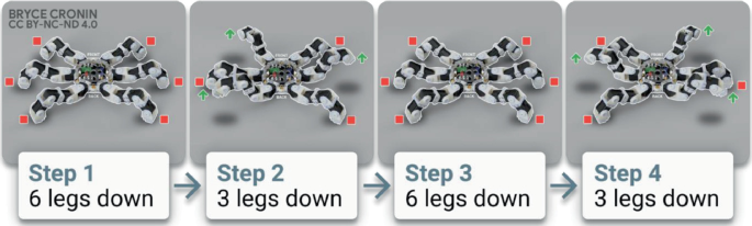
Walking motion. (Bryce Cronin/CC BY-NC-ND 4.0. www.cronin.cloud/hexapod)
-
Unlike traditional hexapod designs that typically have two or three DoF in each limb, this design has four DoF in each limb. This enables the UC hexapod to perform a variety of programmed actions, such seen in Images 20 and 22.
-
It can accommodate a variety of additional attachments such as a gripper, 360° camera, etc. as seen in Image 21.
Image 21 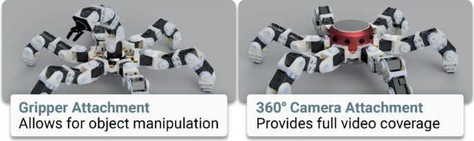
Potential attachment options. (Bryce Cronin/CC BY-NC-ND 4.0. www.cronin.cloud/hexapod)
-
It can flip itself over and continue to perform actions, such as walking while upside down.
-
It can gesture and pose to human collaborators as a method of expressing intention and communication to non-technical personnel in the field such as waving, tapping, beckoning, etc.
-
All the major components were designed to be easy to 3D CAD model, modify and 3D Print. The reason for 3D printing the parts was because it was more cost effective than CNC machining or traditional injection moulding (for such relatively small number of parts). It also avoided having to use expensive of-the-shelf robotic components. Furthermore, because 3D printing was available in house turnaround times could be greatly minimised making it more suited for teaching and research applications .
Image 22 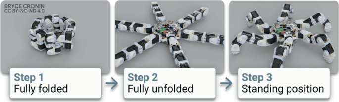
Unfolding motion. (Bryce Cronin/CC BY-NC-ND 4.0. www.cronin.cloud/hexapod)
-
The only off-the-shelf components were the electronic components, all the fasteners, bearings and rubber feet. The off-the-shelf electronic components can be seen in Image 24. The internal off-the-shelf electronic components were configured so that additional electronics could be easily added in the future that can communicate with the existing electronic components. Up to 2 kg of additional electronics and equipment could be supported by the Hexapod Robot design.


The new 3D CAD model of the Hexapod Robot enabled further refinements to the CAD model and verified the fitment of all the parts (tolerances).
Prototyping the Redefined Design: From the refined CAD model, one fully functional prototype of the Hexapod Robot was made as seen in Image 23. This involved 3D printing all the components designed by the two UC honours students on an in-house FDM printer. The material used was polylactic acid (PLA), a thermoplastic made from renewable resources in the form of a filament. The FDM process and PLA material were selected because of their low cost, the parts produced have adequate strength to meet the design requirements, and the process is simple. All the electronic components (see Image 24) and fasteners were purchased off-the-shelf. The prototype was fully tested to verify the assembly, fitment, articulation of the parts, the electronics and the ROS.

Hexapod Robot working prototype

Off-the-shelf electronic components and diagram
Testing the Redefined Design: The tests found that the Hexapod Robot met all the requirements of the design criteria. The tests only found one issue with the design, where the bolts around the joints would unscrewing themselves.
Final Design Prototyping and Documentation (Design Process Step 4)
To address the issue of the bolts around the joints unscrewing themselves, the Hexapod Robot CAD model’s leg members were redesigned to include bearings at the joints. The difference in the design of the leg member can be seen in Images 25 and 26 with the latter being the redesigned version. The bearings can be seen in exploded CAD model of the leg assembly seen in Image 27.

Leg design with problem of the bolts unscrewing themselves circled in red

Final leg design with unscrewing problems resolved circled in red. (Bryce Cronin/CC BY-NC-ND 4.0. www.cronin.cloud/hexapod)

UC Hexapod Robot Leg 3D CAD model exploded view. Built in Fusion 360 CAD. (Derivative of 'Anansi Hexapod Robot' by Bryce Cronin/CC BY 4.0. www.cronin.cloud/hexapod)
The final 3D CAD model of the Hexapod Robot is seen in Images 28, 29 and 30. In the CAD exploded views of the Hexapod Robot model, see Images 27 and 29, the modular design of the parts and the assembly can be seen.

UC Hexapod Robot 3D CAD model. Built in Fusion 360 CAD software. (Derivative of 'Anansi Hexapod Robot' by Bryce Cronin/CC BY 4.0. www.cronin.cloud/hexapod)

UC Hexapod Robot 3D CAD model exploded view. Built in Fusion 360 CAD software. (Derivative of 'Anansi Hexapod Robot' by Bryce Cronin/CC BY 4.0. www.cronin.cloud/hexapod)

UC Hexapod Robot rendered 3D CAD model. Built in Fusion 360 CAD software. (Bryce Cronin/CC BY-NC-ND 4.0. www.cronin.cloud/hexapod)
The final 3D CAD model parts for one leg assembly and the central body can be seen in Image 31 with a description of the parts in Table 12.7. Because of the modular design of the Hexapod Robot, there are only 11 different 3D-printed parts. This included three different printed parts for the central body and eight different printed parts for all the leg assemblies as shown in Image 31.

UC Hexapod Robot final design showing the 3D-printed parts for one leg and the central body. For the description of all the parts, refer Table 12.6. (Derivative of 'Anansi Hexapod Robot' by Bryce Cronin/CC BY 4.0. www.cronin.cloud/hexapod)
Prototyping and Testing the Final Design: The new parts that make up the robot’s central body and one leg assembly were individually saved to STL format and 3D printed. The printing process and material for each part are shown in Table 12.7, importantly these are same as those used in the final manufactured Hexapod Robot to test their validity. The printed parts together with their off-the-shelf electronic components, bearings and fasteners were assembled and tested. The test results found that the unscrewing problems at the joints had been resolved and that the final design fulfilled all the design criteria.
Documentation: This included- 1. A Fusion 360 (parametric) 3D CAD model of the complete Hexapod Robot assembly, 2. user manual and 3. final report with an overview of the development process and recommendations for future development for the Hexapod Robot.
The Contents of the User Manual Were as Follows:
-
1.
Cover page with an image of the Hexapod Robot
-
2.
Images of all the parts complete with parts list. The parts list included a description of each part, materials, manufacturing process, suppliers and quantity.
-
3.
Assembly instructions.
-
4.
Operating instructions.
-
5.
Images of the Hexapod Robot performing all its different functions.
-
6.
Software.
-
7.
Programming (coding) instructions.
-
8.
Technical specifications.
-
9.
Manufacturing instructions for the 3D-printed parts.
-
10.
Maintenance instructions.
Recommendations for Future Development Included:
-
1.
To develop a portable method of powering the robot such as batteries. Currently, the Hexapod Robot is powered by a tethered power source. Importantly, all the electronic components used in the Hexapod Robot will support batteries and require no further modifications.
-
2.
To further develop the electronic hardware to expand the Robot’s functionality.
-
3.
To further develop the software to refine the walking gaits and gesturing movements.
Manufacturing (Design Process Step 5)
To manufacture the Hexapod Robot, all the parts modelled on Fusion 360 (parametric) CAD software by the two UC honours students were individually saved to STL format. All except two of the parts were printed on an SLS 3D printer from Nylon 12 (as seen in Table 12.7). The reason for selecting this printing process and material is because the parts produced would have very good mechanical properties that are suitable for working applications along with high-dimensional accuracy and high-quality surface finish. The remaining two parts were printed on an SLA printer from translucent and ridged acrylate-based plastic (as seen in Table 12.7). This process and material were chosen because of the almost transparent look and very good mechanical properties making the part suitable for functional use.
All the electronic components, as seen in Image 24, and fasteners were purchased of-the-shelf.
Assembly, Testing and Delivery: A fully functional Hexapod Robot was assembled as seen in Images 32 and 33. The Hexapod Robot was fully tested and fulfilled all the design criteria.

UC Hexapod Robot final design being assembled. The description of all the parts refer Table 12.6. (Bryce Cronin/CC BY-NC-ND 4.0. www.cronin.cloud/hexapod)

Final working UC Hexapod Robot. (Bryce Cronin/CC BY-NC-ND 4.0. www.cronin.cloud/hexapod)
A fully functioning Hexapod Robot (see image 36) complete with documentation (1. A full Fusion 360 (parametric) CAD model, 2. User manual and 3. Final report with an overview of the development process and recommendations for future development for the Hexapod Robot) was delivered on time and on budget.
14 Revision Questions
-
Question 1. When in the design process should you identify the materials and processes and why?
-
Question 2. When during the design process can CAD be employed?
-
Question 3. What do you need to do before sending files to a manufacturer?
-
Question 4. Where should a working prototype be tested?
-
Question 5. How many different 3D CAD modelling systems are there, what are they called, and what are their comparative advantages and disadvantages?
-
Question 6. Name the different types of 3D parametric CAD model files?
-
Question 7. What is a circular reference and how do you avoid them?
-
Question 8. What elements should be used as references and what are they?
-
Question 9. What features should not be used as references?
-
Question 10. What features should be creates last in a part file?
-
Question 11. What are CAD drawing files used for?
-
Question 12. Why are technical drawing standards important?
-
Question 13. Technical drawing sheets are typically organised in how many groups and what are they?
-
Question 14. What are orthographic projections and what is their purpose?
-
Question 15. What is VR and AR typically used in CAD for?
-
Question 16. What are some advantages and disadvantages of 3D printing?
-
Question 17. What is the difference between the following two 3D printing methods: SLA and SLS?
-
Question 18. Why is it important to include all the part in a model including off-the-shelf parts?
References
Alba, M. (Retrieved 2018, March). https://www.engineering.com/story/whats-the-difference-between-parametric-and-direct-modeling.
Aloor, J. J., Sahana, P. S., Seethal, S., Thomas, S., & Pillai, M. R. (2016, March). Design of VR headset using augmented reality. In 2016 international conference on electrical, electronics, and optimization techniques (ICEEOT) (pp. 3540–3544). IEEE.
Ault, H. K., & Phillips, A. (2016). Direct modeling: Easy changes in CAD?
Bodein, Y., Rose, B., & Caillaud, E. (2014). Explicit reference modeling methodology in parametric CAD system. Computers in Industry, 65(1), 136–147.
Bonollo, E. (2016). Product design: a course in first principles. Upfront Publishing, Calwell, A.C.T.
Cabero-Almenara, J., Barroso-Osuna, J., Llorente-Cejudo, C., & Fernández Martínez, M. D. M. (2019). Educational uses of augmented reality (AR): Experiences in educational science. Sustainability, 11(18), 4990.
Chen, M. Y., Skewes, J., Daley, R., Woodruff, M. A., & Rukin, N. J. (2020). Three-dimensional printing versus conventional machining in the creation of a meatal urethral dilator: Development and mechanical testing. BioMedical Engineering OnLine, 19(1), 1–11.
Cronin, B. (2020). www.cronin.cloud/hexapod.
Dam, R., & Siang, T. (2018). What is design thinking and why is it so popular. Interaction Design Foundation.
Dávila, J. L., Neto, P. I., Noritomi, P. Y., Coelho, R. T., & da Silva, J. V. L. (2020). Hybrid manufacturing: a review of the synergy between directed energy deposition and subtractive processes. The International Journal of Advanced Manufacturing Technology, 1–14.
Design Council. (2021). https://www.designcouncil.org.uk/news-opinion/what-framework-innovation-design-councils-evolved-double-diamond. Accessed 11 Dec 2021
Elser, A., Königs, M., Verl, A., & Servos, M. (2018). On achieving accuracy and efficiency in additive manufacturing: Requirements on a hybrid CAM system. Procedia CIRP, 72, 1512–1517.
Farshid, M., Paschen, J., Eriksson, T., & Kietzmann, J. (2018). Go boldly!: Explore augmented reality (AR), virtual reality (VR), and mixed reality (MR) for business. Business Horizons, 61(5), 657–663.
Ge, Q., Li, Z., Wang, Z., Kowsari, K., Zhang, W., He, X., Zhou, J.& Fang, N. X. (2020). Projection micro stereolithography based 3D printing and its applications. International Journal of Extreme Manufacturing, 2(2), 022004.
ISO 128. (Retrieved 2021). https://www.iso.org/ics/01.100.01/x/.
ISO. (Retrieved 2021). https://www.iso.org/home.html.
Jammalamadaka, U., & Tappa, K. (2018). Recent advances in biomaterials for 3D printing and tissue engineering. Journal of Functional Biomaterials, 9(1), 22.
Jezernik. (2003). A solution to integrate computer-aided design (CAD) and virtual reality (VR) databases in design and manufacturing processes. The International Journal of Advanced Manufacturing Technology, 22(11–12). https://doi.org/10.1007/s00170-003-1604-3.
Keane, P. (May 2019). VR in CAD: Where are we now? https://www.engineering.com/story/vr-in-cad-where-are-we-now.
Kridli, G. T., Friedman, P. A., & Boileau, J. M. (2021). Manufacturing processes for light alloys. In Materials, design and manufacturing for lightweight vehicles (pp. 267–320). Woodhead Publishing.
Latif, K., Adam, A., Yusof, Y., & Kadir, A. Z. A. (2021). A review of G code, STEP, STEP-NC, and open architecture control technologies based embedded CNC systems. The International Journal of Advanced Manufacturing Technology, 1–18.
Liu, Z., Zhang, H. C., Peng, S., Kim, H., Du, D., & Cong, W. (2019). Analytical modeling and experimental validation of powder stream distribution during direct energy deposition. Additive Manufacturing, 30, 100848.
Ngo, T. D., Kashani, A., Imbalzano, G., Nguyen, K. T., & Hui, D. (2018). Additive manufacturing (3D printing): A review of materials, methods, applications and challenges. Composites Part b: Engineering, 143, 172–196.
Ogunsanya, M., Isichei, J., Parupelli, S. K., Desai, S., & Cai, Y. (2021). In-situ droplet monitoring of inkjet 3D printing process using image analysis and machine learning models. Procedia Manufacturing, 53, 427–434.
Prud’homme van Reine, P. (2017). The culture of design thinking for innovation. Journal of Innovation Management, 5(2), 56–80.
Shahrubudin, N., Lee, T. C., & Ramlan, R. (2019). An overview on 3D printing technology: Technological, materials, and applications. Procedia Manufacturing, 35, 1286–1296.
Spasova, N., & Ivanova, M. (2020). Towards augmented reality technology in CAD/CAM systems and engineering education. In The international scientific conference eLearning and software for education (vol. 2, pp. 496–503). " Carol I" National Defence University.
Standards Australia, AS1100.101–1992 (1992).
Tornincasa, S., & Di Monaco, F. (2010, September). The future and the evolution of CAD. In Proceedings of the 14th international research/expert conference: trends in the development of machinery and associated technology (vol. 1, No. 1, pp. 11–18).
Williams, R. A. (1993). Engineering drawing handbook. Standards Australia.
Wong, K. (2019, December). Is AR/VR ready to go beyond visualization? https://www.digitalengineering247.com/article/is-ar-vr-ready-to-go-beyond-visualization/cad.
Xometry (Retrieved 2020, May 27). https://xometry.eu/en/choosing-right-file-formats-for-manufacturing/.
Author information
Authors and Affiliations
Corresponding author
Editor information
Editors and Affiliations
Rights and permissions
Open Access This chapter is licensed under the terms of the Creative Commons Attribution-NonCommercial-NoDerivatives 4.0 International License (http://creativecommons.org/licenses/by-nc-nd/4.0/), which permits any noncommercial use, sharing, distribution and reproduction in any medium or format, as long as you give appropriate credit to the original author(s) and the source, provide a link to the Creative Commons license and indicate if you modified the licensed material. You do not have permission under this license to share adapted material derived from this chapter or parts of it.
The images or other third party material in this chapter are included in the chapter's Creative Commons license, unless indicated otherwise in a credit line to the material. If material is not included in the chapter's Creative Commons license and your intended use is not permitted by statutory regulation or exceeds the permitted use, you will need to obtain permission directly from the copyright holder.
Copyright information
© 2022 The Author(s)
About this chapter

Cite this chapter
Pianca, E. (2022). The Embedded Design Process: CAD/CAM and Prototyping. In: Herath, D., St-Onge, D. (eds) Foundations of Robotics. Springer, Singapore. https://doi.org/10.1007/978-981-19-1983-1_12
Download citation
DOI: https://doi.org/10.1007/978-981-19-1983-1_12
Published:
Publisher Name: Springer, Singapore
Print ISBN: 978-981-19-1982-4
Online ISBN: 978-981-19-1983-1
eBook Packages: Intelligent Technologies and RoboticsIntelligent Technologies and Robotics (R0)