
Abstract
Motors are the most important executive components in electrical automation equipment, including AC motors, DC motors, AC servo motors, DC servo motors, stepping motors, etc. In the design of the automation system, the selection of the motor is a frequently encountered problem. You need to calculate the parameters of the required motor. Novices often do not know where to start. Below we give a simple calculation and selection method.
You have full access to this open access chapter, Download chapter PDF
Motors are the most important executive components in electrical automation equipment, including AC motors, DC motors, AC servo motors, DC servo motors, stepping motors, etc. In the design of the automation system, the selection of the motor is a frequently encountered problem. You need to calculate the parameters of the required motor. Novices often do not know where to start. Below we give a simple calculation and selection method.
11.1 Determination of the Rated Torque Ne of the Motor
The selection of the motor is mainly based on the calculation of the rated torque, and the rated torque Ne of the motor should meet:
Among them, NW is the load torque, and Nf is the resistance torque of the equipment.
The load torque Nw includes the constant speed load torque Nc and the variable speed load torque Nad. the variable speed load torque Nad includes the acceleration load torque Na and the deceleration load torque Nd. The variable speed load torque Nad takes the maximum value of Na and Nd.
The equipment resistance torque Nf includes the equipment static resistance torque Nfs and the equipment motion resistance torque Nfw. Generally, the equipment static resistance torque Nfs is greater than the equipment movement resistance torque Nfw, and the resistance moment of the equipment is considered based on the static resistance moment of the equipment.
-
1.
Calculation and determination of resistance torque
For the improvement of existing equipment, it is obtained by experimental methods. If it is new equipment, according to past experience or references, if no relevant data can be found, the static resistance torque of the equipment must be obtained by calculation methods. It is recommended that novices do not continue because the calculation process is complicated and the calculated results may not be correct. We suggest that if readers are inexperienced, they should not consider the resistance moment first, only the load moment, and then increase margin coefficient, which will make it easier to get started.
When obtaining the static resistance torque of the equipment by experiment, first remove the coupling between the motor and the connecting shaft. Three simple measurement methods are as follows:
-
(1)
Use a torque wrench (or torque electric wrench) to rotate the connecting shaft, and the torque value that makes the connecting shaft just rotate is the resistance torque value of the equipment. Write down the torque reading. The torque wrench is shown in Fig. 11.1.
Fig. 11.1 
Torque wrench
-
(2)
Tie one end of a rod (such as a piece of wood or iron rod) to the connecting shaft with a nylon cable tie (or wire), or clamp a large wrench on the connecting shaft, as shown in Fig. 11.2.
Fig. 11.2 
Test resistance torque


The rod is placed horizontally and perpendicular to the connecting shaft. The weight of the rod is W1 (kg, kilogram force). An object (such as several nuts, or small pieces) is hung on the other end of the rod. The length of the connecting shaft to the object is L (m, m), increase the weight of the object to W2 (kg), until the connecting shaft starts to rotate. If there is a tension scale, it can also be replaced by a tension scale. Read the kilogram force W2 of the tension scale when the connection shaft just starts to rotate the conversion of kg into N needs to be multiplied by the acceleration of gravity g, then the resistance moment Nf (N · m) is equal to
-
(3)
If the method of fixing a rod on the connecting shaft is limited, a binding rope (or material tape) can also be wound on the connecting shaft. The radius of the connecting shaft is R (m), and the binding rope (or material tape) The other end is connected to a tension scale, as shown in Fig. 11.3.
Fig. 11.3 
Test resistance torque

Pull the binding rope (or material belt) hard, and record the kilogram force reading W2 (kg) of the tension scale when the connecting shaft starts to rotate, then the resistance torque Nf (N · m) is equal to
If it is inconvenient to remove the coupling between the motor and the connecting shaft, or it is inconvenient to fix the rod (or wrap the packing rope) on the connecting shaft. It is necessary to consider other shafts (connected with the connecting shaft) to measure. The transmission mode and the transmission ratio will affect the calculation of resistance torque, which will be explained later when we talk about load torque measurement.
-
2.
Calculation and determination of constant speed load torque
-
(1)
For rotating loads directly driven by the connecting shaft;
-
(1)
If it is cutting head of cutting machine tool or digging head of mining excavation equipment, etc., as shown in Fig. 11.4.
Fig. 11.4 
Cutting torque
-
(1)
-
(1)

The constant speed load torque Nc is equal to the cutting force F multiplied by the cutting head radius R1.
-
(2)
If it is a printing machine, rotary die-cutting machine or paper machine, etc., as shown in Fig. 11.5.
Fig. 11.5 
Uniform speed load torque

The total pulling force F1 minus the total pulling force F2, the constant speed load torque Nc is
where F1 is the sum of the tensions of the various strips passing through the work roll 1, and the force opposite to the rotation direction of the coupling shaft. F2 is the total amount of tension of strips and scraps after processing.
The force relationship in gear transmission or rubber roller transmission is shown in Fig. 11.6. The force at the edge of each gear is constant, but the torque of each gear is different.

The relationship between gear transmission and force
-
(2)
For linear motion loads, such as CNC machine tools, machining centers, assembly machines, etc., the connecting shaft drives the ball screw, and the screw nut drives the worktable to perform linear motion. The pitch of the ball screw is h, as shown in Fig. 11.7.
Fig. 11.7 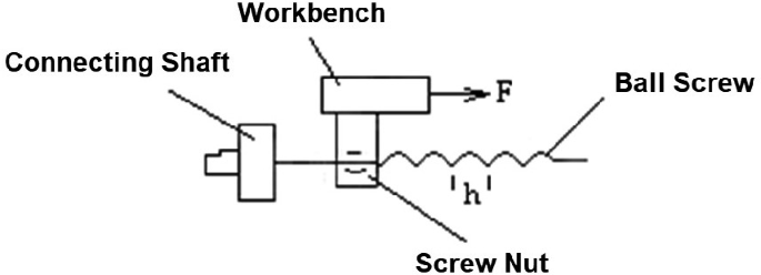
Linear motion load

The connecting shaft rotates once, and the movement angle is 2π radians. At the same time, the ball screw rotates once, and the screw nut drives the worktable to move linearly with a pitch h (m), and the thrust of the worktable is F (N). According to the principle of energy conservation, the uniform speed load moment Nc (N · m) is
-
3.
Calculation and determination of variable speed load torque
The calculation of acceleration torque and deceleration torque is the same, but the torque direction is opposite, so we only discuss the calculation of acceleration torque.
-
(1)
For rotating loads.
An object with a mass of m (kg) rotates around a radius r (m), its linear velocity is V (m/s), its angular velocity is ε, and its kinetic energy W is
The moment of inertia J(kg · m2) is defined as
For a uniform disk with a diameter of R (m) and a total mass of m (kg) or a uniform circular shaft with a length of L, its moment of inertia J (kg · m2) is
An object with a moment of inertia J and an angular velocity ε passes through a reducer (or gear, synchronous belt), the reduction ratio is n, the angular velocity is nε, and the equivalent moment of inertia is J′. Regardless of friction, the kinetic energy on both sides is equal. Out of the equivalent moment of inertia J′ on the other side of the reducer,
All the k work rolls that are driven by the connecting shaft, the transmission ratio with the connecting shaft is n1, n2, … nk. Their moments of inertia are J1, J2, … Jk. The moment of inertia converted to the connecting shaft on the motor side is J1d, J2d, … Jkd. The moment of inertia of the motor is Jm, then the total moment of inertia J converted to the motor side is
According to the speed requirements of the equipment, converted to the connecting shaft, the time for the angular velocity of the connecting shaft to accelerate from 0 to ε is t (s), and the torque required on the connecting shaft is Nad (N · m), which is the speed change torque that the motor needs to provide.
If there is a reducer between the connecting shaft and the motor, the connecting shaft torque Nad (N · m) speed n1 (rpm). After passing through the reducer with a reduction ratio of n, the torque converted to the motor side is Nad'(N · m) and the speed is n2 (rpm). Regardless of friction, the power on both sides of the reducer is equal, and the speed change torque \(N_{ad^{\prime}}\) (N · m) on the motor side is obtained
-
(2)
For linear motion loads.
The connecting shaft drives the ball screw, and the screw nut drives the worktable. The mass of the screw nut and the worktable is m1 (kg), and the worktable drags an object with a mass of m2 (kg) to make a linear motion, as shown in Fig. 11.8.

Linear motion load
The time for the object to accelerate from 0 to Vmax (m/s) is t (s), and the force F (N) that the workbench needs to apply is
Regardless of the friction, the work done on the side of the connecting shaft and the side of the table is equal, and the acceleration torque Nad1 converted to the side of the connecting shaft is given by
The moment of inertia of the connecting shaft, lead screw and motor is J. When the speed of the object accelerates from 0 to Vmax (m/s) within time t (s). The angular velocity of the connecting shaft and lead screw accelerates from 0 to εmax (rad/s). The acceleration torque Nad2 required on the connecting shaft
The total acceleration torque Nad required by the motor
11.2 Determination of Motor Speed
The motor speed is determined according to the highest working speed required by the automation equipment.
For the load shown in Fig. 11.9, the maximum speed V (m/min) of the material belt corresponds to the maximum speed nmax (rpm) of the work roll 1.

Tape load
The maximum speed of the connecting shaft and work roll 1 is the same, equal to
For the load shown in Fig. 11.8, if the maximum linear motion velocity of the known object is Vmax, the maximum angular velocity converted to the motor side of the connecting shaft is εmax (rad/s). The maximum rotational speed is nmax (rpm).
Select the rated speed of the motor ne
11.3 Determination of the Maximum Acceleration of the Servo Motor
According to the process conditions, general motion loads have an acceleration requirement. For example, the time required to increase the speed of the material belt (or paper) from 0 to the maximum speed Vmax (m/s) does not exceed t (s). The acceleration of the material belt a (m/s2) for
Referring to the method in Sect. 11.2, calculate the maximum angular velocity εmax (rad/s) of the motor connection shaft according to the maximum vehicle speed Vmax (m/s). Then the angular acceleration ω (rad/s2) of the connection shaft is
The maximum angular acceleration ωmax of the servo motor must satisfy
If a reducer is installed on the front of the servo motor, and the reduction ratio is n, the maximum angular acceleration ωmax of the servo motor must satisfy
Otherwise, the driver of the servo motor will give an alarm during acceleration.
11.4 Determination of Motor Power
The power P(kw) of the motor is equal to
11.5 Determination of Encoder Resolution
The selection of encoder resolution is determined according to the processing accuracy required by the automation equipment. For example, in Fig. 11.7, the positioning accuracy A of the material strip is required to be 0.1 mm. The diameter R1 of the work roll 1 is 50 mm, the circumference L of the work roll 1 is 2πR1 = 314.16 mm, and the connecting shaft of the work roll 1 is installed for the motor. The minimum resolution Re of the encoder should be L/A = 3140. In order to leave room for adjustment of the PID and feed-forward parameters of the positioning link, the resolution of the encoder should be increased by an order of magnitude, that is, greater than or equal to 31,400.
11.6 Servo Motor Inertia Ratio
Servo motor inertia ratio λ: refers to the ratio of the load's moment J of inertia to the motor's moment Jm of inertia.
For a fixed load, when λ increases, the response speed of the system will slow down and the control accuracy will decrease. λ is generally between 5:1 and 10:1. For some low-speed motion situations, λ can be selected between 3:1 and 5:1.
It is best to select this parameter according to the technical specifications provided by the servo motor manufacturer, otherwise it will seriously affect the control accuracy and dynamic response speed of the system.
Author information
Authors and Affiliations
Corresponding author
Rights and permissions
Open Access This chapter is licensed under the terms of the Creative Commons Attribution 4.0 International License (http://creativecommons.org/licenses/by/4.0/), which permits use, sharing, adaptation, distribution and reproduction in any medium or format, as long as you give appropriate credit to the original author(s) and the source, provide a link to the Creative Commons license and indicate if changes were made.
The images or other third party material in this chapter are included in the chapter's Creative Commons license, unless indicated otherwise in a credit line to the material. If material is not included in the chapter's Creative Commons license and your intended use is not permitted by statutory regulation or exceeds the permitted use, you will need to obtain permission directly from the copyright holder.
Copyright information
© 2024 The Author(s)
About this chapter

Cite this chapter
Yao, F., Yao, Y. (2024). Calculation and Selection of Motor Parameters in Automation System. In: Efficient Energy-Saving Control and Optimization for Multi-Unit Systems. Springer, Singapore. https://doi.org/10.1007/978-981-97-4492-3_11
Download citation
DOI: https://doi.org/10.1007/978-981-97-4492-3_11
Published:
Publisher Name: Springer, Singapore
Print ISBN: 978-981-97-4491-6
Online ISBN: 978-981-97-4492-3
eBook Packages: Intelligent Technologies and RoboticsIntelligent Technologies and Robotics (R0)